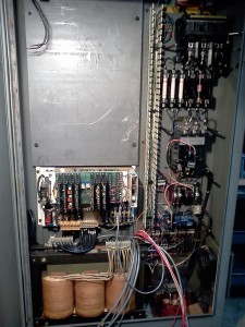
This is the control enclosure, after stripping out everything that we decided we wouldn’t need, or that was being replaced. The plate in the upper left is where all of the new stuff will be located, along with some of the original stuff.
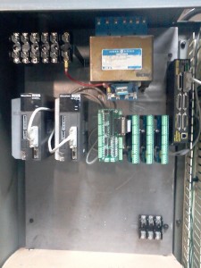
This is a view of the new plate with most of the required equipment mounted. We are still lacking some power supplies and perhaps a few other things, but there is still room. Hopefully everything we end up needing will fit on the panel.
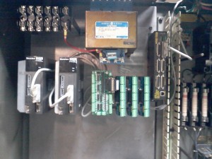
This is a closer view of the top of the new panel. The original control transformer is at the top center, with some of the original fuse blocks to the left of it.
The Z drive is on the left, with the X drive next to it.
To the right of the drives are the I/O module, and 3 25 pin breakout modules.
The motion controller is mounted vertically on the right edge of the panel.
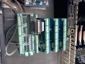
A closer view of the I/O and breakout modules.
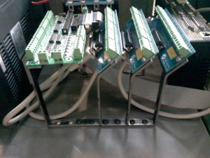
We stood the modules off the panel for easier access, and for cable management. The breakout modules are mounted at a 45 degree angle to the panel, to allow the 25pin connector to flow back toward the panel.
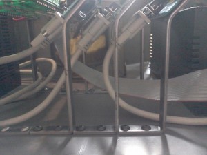
This view shows how the modules are stood off from the panel. This arrangement allowed for the modules to fit in a much smaller space than laying them flat. It also allows for good access to the terminals. The cables will fit in the space below the modules, which will hide some of the messiness of using pre-made cables.
This is looking straight up in the air at the brackets holding the modules. You can see how the connectors overlap each other.
The brackets were made from 1/2 by 1/8 cold rolled steel, which forms easily enough to do this work with common tools. (hammer and vice) Cold rolled in this size easily takes 90 degree sharp bends without breaking or weakening significantly.

